Thursday, November 20, 2008

NTS & B Helix exit track / graduated trestle complete

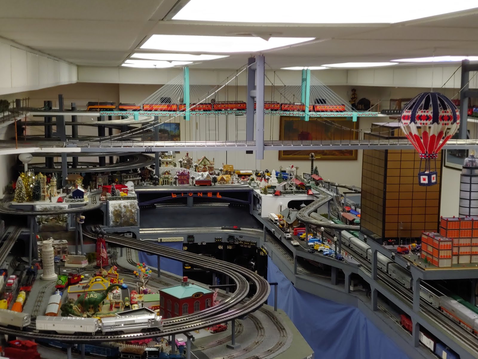
The lower helix exit is mounted on the Lionel Graduated Trestle set, bringing the helix loop down to the winter level. At this level, the track will make a raised loop over the mainline yard, and then go back up the other track on the trestle. The winter table top has been repainted white, to faciliate the upcoming snow.


Wednesday, November 19, 2008

NTS & B Helix Wiring Cleaned up & Norway Pics

I finally got time to clean up the wiring at the bottom of the helix (See June 27, 2008 post). I wanted to try to get the winter layer going so I could set up a Christmas scene, but decided I had to get the helix wiring done first.

Of course, I had to take a little 'detour' to Oslo, Norway for 2 weeks also. Here are a couple pictures of Oslo, and a nice little train store we visited while there.


Monday, October 20, 2008

NTS&B A few Oct 2008 pictures

Scott and Maria were down this weekend, and we got a little camera happy with the upper level. This picture is of Maria standing on her tippy toes looking at the Polar Express from the inside of the Helix.
Here's a good picture of me working on the second (cable stayed) bridge. Talk about having your head in the clouds :)

Here's a picture Maria took of the helix from the inside, looking from the bottom up. I asked her to take one looking down from the top, but for some reason she wouldn't do it :)


Wednesday, October 15, 2008

NTS & B First 3 of 5 power stations complete

The first 3 power station shelves are completed. Instead of having 1 huge central control panel, I decided to have a distributed power design. Each power station will house all of the transformers to control 1 or 2 levels, and will be positioned close to the tracks and accessories they will control.

The station on the left will control the Subway level. The only additional switches required so far control the station stop, and are fastened to the power distribution box directly above the transformer.

The center station will control the Winter and Helix levels. Switches for the overhead level power and switch tracks will be located on the underside of the bridge directly above this station. The location of the controls for the winter level switches and accessories is yet to be determined, but will be probably on the front of the subway bench work directly over the station.

The station on the right will control the mainline tracks, yard, and switches. The yard power switches are located on the mainline layer directly over the power station. Also housed in the mainline station is the Train Master Command Control (TMCC) module, and the Train Power Control (TPC) module. The TMCC module sends digital commands for remote control to engines that are equipped with the TMCC receives. The TPC controls the track power for 1 track, and can be used to remotely control older 'conventional' locomotives. The output of this TPC will go to a power distribution module in each power station. The module will have switches to select the TPC or local transformer control. This will allow the remote controlled voltage to be switched to any track, to make troubleshooting problems easier at remote locations.

There will eventually be 2 more stations located at the other end of the layout, one on each side of the isle. These will be located close to the operating accessories in these areas.

Saturday, October 4, 2008

NTS & B Second attempt on cable stayed bridge

Am trying a different type of nylon cord. Cord I first used was clear. I was trying to use LEDs to change the color on demand, but the cords would not show up. The cord on the side closest to the camera is light blue weed-eater string. Shows up a little better in they daylight, but no help with the LEDs. So much for that idea. I plan on restringing the other side with the blue cord when time permits.


Friday, October 3, 2008

NTS & B Second power station started

Second (of 5) transformer shelf is built, waiting for paint. Shelf is in approximate position. Leg brace will have to be trimmed before if will fit where it is supposed to. Unit is app 18 inch wide, 30 inch tall, and made out of 1x12 with a plywood backing.

NTS & B last winter level table finished

The last of the winter level tables is now complete and installed. Need to paint some supports. Gaps between the 2 layers will eventually be filled in with foam 'stone' walls, or a steep rock wall. Module is approximately 3 ft x 6 ft, and made out of 1x4 and 1x2 frame covered with 1/2 inch 4 ply plywood.


Saturday, September 20, 2008

NTS & B Second major bridge started

Sep 2008 - Decided that the bridge for the second room crossing should be a different then the suspension bridge used for the first one. This one will be a 'cable stayed' type. This is the first tower up, with one side strung. I am using nylon line, with the plan of adding colored LEDs or wheat bulbs to change colors on the lines (at least that is the plan).


Tuesday, September 9, 2008

Some videos

Use the "YouTube Channel" bar on the right to view other videos like this one.

The new bridge is FINALLY open on the North Pole Line. This is video of the Polar Express topping the helix and crossing the bridge.


Wednesday, September 3, 2008

NTS&B Suspension Bridge Construction Notes

The bridge is now finished. The first couple pictures are of the completed bridge. Pictures of the construction are below and in order of construction.


Measurements / Construction Notes:

  • Main (Horizontal) cables were made from 1/8 in steel cables.
  • Vertical cables are made of cotton embroidery thread which are fed through #2 13/16 inch long eyelets, wrapped around top cable and tied. The thread is sightly stretch, so holds in place very well. A dab of hot glue was applied to the threads on the steepest part of the cable to make sure it doesn't slip. Caution, do not use super glue, as it bonds the fibers of the thread, and the thread becomes totally brittle.
  • Eyelets are deck spaced every 2 inches on the bridge deck, and start at 2 inch from edge of tower
  • Tower is 17 1/2 inch tall from top of deck, and hangs down 1 3/4 inch below deck
  • Deck to bottom of lower cross brace between towers is 9 inches, and 14 inches to bottom of upper cross brace.
  • Deck is made of 1x12x8, and is app 12 1/2 ft long total
  • Overall length of deck from first cord on first tower to last cord on last tower is 120 inches
  • Towers are made of 2 1x2's shaved and shaped with a router. The inside one rests on the deck, and has a grove routed in it for the all thread support rod and wires for the blinking LEDS. The cross piece is screwed to the inside pieces. The outside pieces are longer, and hang below the deck.
  • Bridge holds 1 O-27 and 1 GScale tracl
Initial 1x12 bridge deck with towers

Close up of inside of bridge tower

A template was used to approximate main cables shape. Curve was first plotted on computer, then points measured every 2 inches and marked on template. Screws were then placed at the selected points.

Template in place on bridge cable. Template was clamped in position on the main cables, then the verticals were tied at each screw location.


A cable clamp was used on each end of steel cable to control the tension.
A 1x2 with routed grove was used to hold cable in position.
Eyelets were screwed into bottom of deck at 2 inch intervals to hold verticals. The bridge deck was made from 2-8 foot boards, which were routed and overlapped in the middle for additional support as shown above.
Closeup of knots at top of cable


Tower with outside 1x2 attached.

Picture showing vertical mesurments of tower

Picture showing horizontal mesurments of deck