Monday, August 13, 2007

NTS & B Train room finished

Aug 2007 - Room is finally finished. Ceiling, wall, carpet, and doors ! FInally ready to start thinking about building the layout. Room size is 15 ft 6 inches x 40 ft


Monday, August 6, 2007

NTS & B Layout plan taped on floor


August 2007 - Room is finally finished, minus the carpet. Taped outline of layout on the floor to get better feel of isles. Outside isle was a little tight, so ended up narrowing the layout 6 and stretching the length 6 inches to get better clearances. Of course, now model is off a bit :(

Friday, March 23, 2007

NTS & B Layout Model

March 2007. - These pictures are of a scale model of the layout. Since the layout is multi layered, I needed a model so I could visualize access from underneath the layout. When all is said and done, the full layout should be look pretty close to this model. The model was created using the track plan designed in the RR-Track Software Version 4.02. The track plan was created on multiple drawing layers, with each track and table level being on different layers. Each layer was then printed to the same scale. The scale prints were then glued to thin foam board. After the glue dried, the layers were cut out using sissors and an Exacto knife, and then hot-glued together. I even used the model to help design the table framework to ensure clearance from underneath to the upper levels. This framework was also cut out, and glued to the model. The model was printed at 1 inch=1 foot, so the model 12.5 inches x 32 inches. while the layout will be app 12.5 ft wide at the widest end (actual 15 1/2 ft on ceiling), and 32ft long.


Saturday, February 10, 2007

NTS & B Final RR Track Concept views

Feb 2007 - These are the final (7th version) concept views of the planned layout. They show the track plan, and the placement of the various accessories. Room is 40 ft by 15 ft 6 inches. Layout is app 12 ft wide at the widest end (actual 15 1/2 ft on ceiling), and 31 ft 6 inches long. The trackplan was created using RR-Track Version 4.02. The views below were then created using the 3D feature of the program.


Friday, August 11, 2006

NTS & B Train room ceiling finished


Aug 2006 - Finally finished drop ceiling, after only working on it every weekend for a month. OK, so the directions say that a typical room should take about 6 hours for a novice, my room was a little larger :( Directions said typical room had 4 hangers in the center of the room. Mine had over 40 hangers, 68 custom made (by me) L channels, and over 400 pop rivets. Room size is 40 ft by 15 ft 8 inches. Still have doors, carpet, and trim to finish.

Saturday, June 10, 2006

NTS & B - Working on the train room


June 2006 - Lights and heat are in. Finally starting sheet rock in train room. Room is 40 foot long by 15 1/2 foot wide. Man thats a lot of sheet rock.

Thursday, June 1, 2006

NTS&B Helix Construction Notes

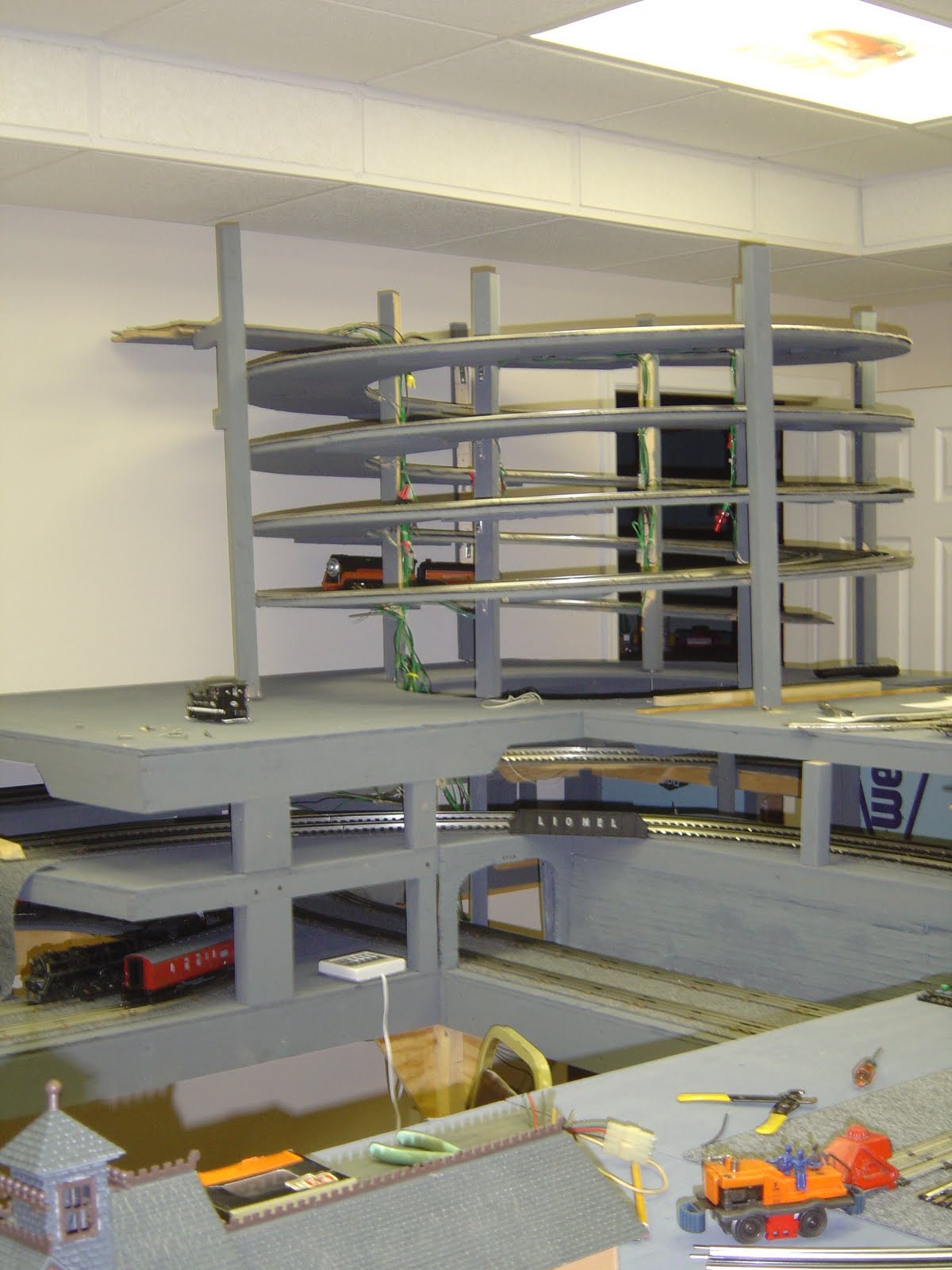
Here are some pictures of the steps used in the construction of the Helix.

I first drew up a scale template to determine how to get the most sections out of 1 sheet of plywood. This template is for 0-54 and 0-42 tracks, with app 2 5/8 inches extra on inside and 1 7/8 extra on the outside for clearance (overall size was 35 inch diam inside, and 58 inch diam outside). I worked with another individual on a fast track helix, and he simply laid the track on the plywood, and used a small compass to draw the lines. http://www.blogger.com/post-edit.g?blogID=5640420068638743046&postID=5389337055289979752
I decided to use external wooden support to try to minimize the overall weight. If I had used Threaded Rods, I would have had to extend the inside and outside dimension of the plywood roadbed at least an inch so the plywood would not warp.


Next I created a home-made, large size compass out of a couple of old yard-sticks


To assemble the pieces, I worked from the top to the bottom of the helix. This allowed me to glue and screw plywood splices, without having to keep the layers separated. The problem with this is you have work backwards on you entry and exit tracks and grade. Before attaching the second layer, make sure you're grade is in the intended direction, and you top exit point is correct. Also, the top and bottom of the helix should have a transistion grade. Make sure to not have any splices near the end of the top exit, or near the end of the level directly above the bottom exit. This gives an extra 1/2 inch clearance to allow the plywood to flex for the transition grade. The next 2 pictures show the final result from the bottom (where you can see the splices), and top (track side). Notice that is is about 5 feet in diameter


Next we put on the legs. Putting this together is like handling a 5 foot wide slinky, so get some help. I used 2x2 legs. Since the rise is 6 inches between layers, that meant that each 1/4 of the turn would be 1 1/2 inches higher than the last one. I laid 4 legs together on a table and offset each one by 1 1/2 inches from the previous one, and clamped them together. Then it was just a matter of drawing a straight line across all 4 legs at 6 inch intervals. Since the inside legs were going to be offset 1/2 way between the outside legs, I repeated the process, but started the first line at 3/4 inch, then used 6 inch intervals. I put lag bolts for levelers at the bottom of each leg to compensate for any inaccuracies in leg placement. The legs were attached using 1 and 2 screw L Brackets and using only screw in each until all brackets were attached, so the brackets could be set a a slight angle. The other major problem when attaching the legs is that there is no level vertical or horizontal reference to help align the legs. I finally ended up using a level on each leg to make sure it was vertically plumb, because visually they all look like they are leaning.


Nest came the carpet roadbed, track, and of course a test train. The carpet was the cheapest grade gray carpet with rubber backing that Lowes carries. My wife came up with a paper template that we pinned to the carpet. and then cut it with had scissors. I have since learned that Black-and-Decker has an electric scissors that works fantastically, and you can put the track down and then trim around it using the track as a guide.

The helix was first set up on the floor, with a temporary turnaround at the top and bottom. Trains of various lengths were run to ensure no problems. One problem I discovered while using the carpet roadbed was that it was hard to keep the tracks level. Track wires were run down the inside of each inner leg. Tacks were wired every 1/4 section (overkill) and I tried to keep all runs the same length. The reason I ran so many feeders was I wanted to minimize any pin corrosion over time, since power was being fed from both sides of 3 tracks maximum.


One of the hardest parts of the project was painting the blessed thing. No matter how many times I touched it up, I would sill find places I missed. The whole helix was painted with Lowes Primer tinted gray. I ended up not putting a top coat on it.


Finally the time came to put it on the layout. First I had to make sure the bench work underneath was built sufficiently robust that it would not only support the helix (which was 2 sheets of plywood plus 2x2 legs and track), but also support myself if I had to stand on it. Then I invited 4 friends over, and it took all five of use to install it, since it was in such an awkward position. Notice also, the supporting bench work also has a whole in the center, so the complete inside of the helix can be accessed. There is even enough room so that a step ladder can be used inside to reach the top level.


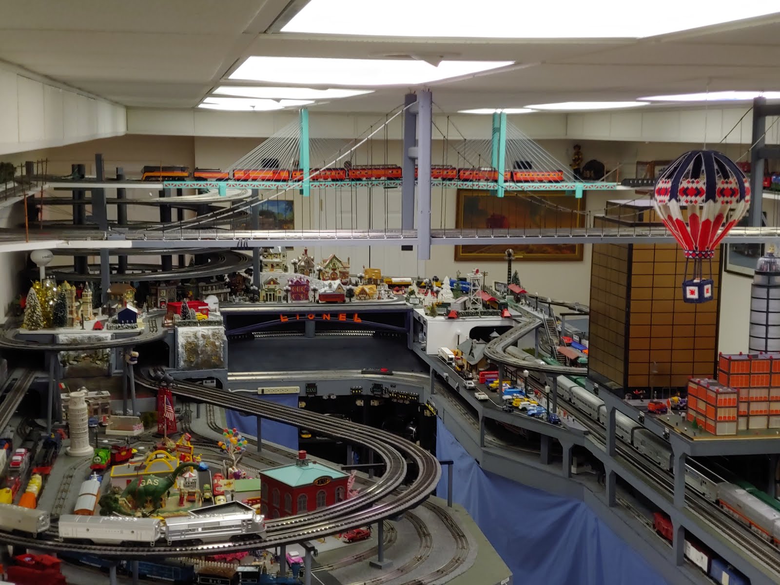
Picture of final result, showing upper and lower level connections. The upper level is attached to a shelf layout containing 2 suspended suspension style bridges (see later posts). The lower level attaches to a Lionel Graduated Trestle set which then has a loop back when it reaches the bottom level The wiring on the inside legs was hidden using inexpensive foam pipe insolation. It is split the entire length, so it just slips over the leg. It is also easy to cut, so you can notch where wires and other obstructions occur. The edges of the foam split have glue on them with a protective plastic cover. The plastic can be removed for perminent installation if desired, but all of mine are just held on by the friction.


NTS & B Helix final attempt

June 2005 to June 2006- The second and final attempt resulted in 6 inch layers (top to top). It has 2 loops. An inner loop of 0-42 diameter track, and an outer layer of 0-54. This resulted in a 4.5% grade on the inside loop, and a 3.5% grade on the outside loop. Although still steep, it is workable. My postwar 2037 will pull 4 (well oiled) postwar passenger up the outside loop. My modern Lionel PA1 handled the B unit and 6 passenger cars. I had to add 1 more layer to maintain the desired height (around 30 inches). Ended up using 2 complete sheets of 1/2 inch plywood. I used 3 ply 1/2 inch plywood for the surface. If I had it to do over, I would use 1/2 inch 4 ply because it is stiffer in both directions.

Overall dimensions - 6 foot diameter, 30 inches tall


The picture above shows a temporary loop connecting the inside and outside tracks of the helix. This will eventually be stretched to go around 1/2 of the top of the room (App 16x20 loop).

The center picture shows a 2037 pulling 3 well oiled post war passenger cars up the grade.

The bottom picture (a year later) shows the planned loop the the bottom of the helix. This will be at table top level around 36 inches from the floor. The year in between was spent arranging for heat and air, and having it installed.


01/16/2011 update:
I suppose it would be a good idea to add the results of the helix outside loop testing. Tests were done using the 7 Polar Express passenger cars, up to 5 additional modern passenger cars, and a box car added to diesels to simulate the tender in the steam engines. Results are as followsL
-Polar Express and most other modern engines pulled up 12 cars or more. A couple of the dual motor modern engines acted like they could pull many more cars without issue.
-624 swither (with magnitraction) only pulled up 8 (plus a simulated tender).
-2026 2x6x4 pulled up 6,
-2020 6x8x6 pullted up 5,
-2037 2x6x4 slipped with 4,
-2018 2x6x4 slipped with 3.
-Also, if I remember right, the 2020 would slip when pulling only 4 well lubricated postwar passenger cars.
-Another note, coming down on the inside is fun also. The 2020 had to be run at such low voltage that the e-unit kept dropping out. To run unattended, cruise control is almost required (which includes MTH PS2 and Loco Sound engnes). The exception is a very low geared engine that won't speed out of control on the way down.


Monday, May 30, 2005

NTS & B Helix first attempt


May 2005 - Kathy had seen a helix on a HO layout a few years back, and made it a requirement that we had one on ours. I decided to build one and test it out, while waiting on the heat and air to be installed. The rest of the layout was designed with the helix included. This was the first attempt. It has 2 loops. An inner loop of 0-42 diameter track, and an outer layer of 0-54. I tried 8 inches between layers, which resulted in 6.1% grade on inner loop, and 4.7% grade on the outer loop. The Williams dual motor F3 is really struggling with the F3B unit and 5 cars. This grade was entirely too steep, so another attempt was required. Putting it together was like putting legs on a six foot diameter Slinky.

Overall dimensions app 6 ft in diameter by 32 inches tall

Thursday, October 30, 2003

Pre NTS & B Layout drawing

This was one of the first attempts for a track plan for the NTS & B. The general shape of the layout is a J, with an isle down the middle, and all the away around except on the wall on the bottom of the diagram. The dual mainline was an over / under design, with 0-72 minimum on the outside track. Every track was connected to another track, so a train could travel to any track. Underneath was a storage yard. I dropped this design because the number of trains that could be run at one time, or easily switched in and out was limited, due to all of the interconnecting tracks. The track plan was drawn using Atlas Right Track Freeware, which is limited to only using Atlas track.