Saturday, October 4, 2008
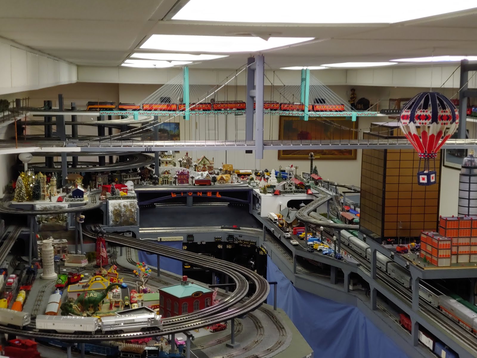
NTS & B Second attempt on cable stayed bridge
Am trying a different type of nylon cord. Cord I first used was clear. I was trying to use LEDs to change the color on demand, but the cords would not show up. The cord on the side closest to the camera is light blue weed-eater string. Shows up a little better in they daylight, but no help with the LEDs. So much for that idea. I plan on restringing the other side with the blue cord when time permits.


Friday, October 3, 2008
NTS & B Second power station started
Second (of 5) transformer shelf is built, waiting for paint. Shelf is in approximate position. Leg brace will have to be trimmed before if will fit where it is supposed to. Unit is app 18 inch wide, 30 inch tall, and made out of 1x12 with a plywood backing.


NTS & B last winter level table finished
The last of the winter level tables is now complete and installed. Need to paint some supports. Gaps between the 2 layers will eventually be filled in with foam 'stone' walls, or a steep rock wall. Module is approximately 3 ft x 6 ft, and made out of 1x4 and 1x2 frame covered with 1/2 inch 4 ply plywood.


Saturday, September 20, 2008
NTS & B Second major bridge started
Sep 2008 - Decided that the bridge for the second room crossing should be a different then the suspension bridge used for the first one. This one will be a 'cable stayed' type. This is the first tower up, with one side strung. I am using nylon line, with the plan of adding colored LEDs or wheat bulbs to change colors on the lines (at least that is the plan).


Tuesday, September 9, 2008
Some videos
Use the "YouTube Channel" bar on the right to view other videos like this one.
The new bridge is FINALLY open on the North Pole Line. This is video of the Polar Express topping the helix and crossing the bridge.
The new bridge is FINALLY open on the North Pole Line. This is video of the Polar Express topping the helix and crossing the bridge.
Wednesday, September 3, 2008
NTS&B Suspension Bridge Construction Notes
The bridge is now finished. The first couple pictures are of the completed bridge. Pictures of the construction are below and in order of construction.

 Measurements / Construction Notes:
- Main (Horizontal) cables were made from 1/8 in steel cables.
- Vertical cables are made of cotton embroidery thread which are fed through #2 13/16 inch long eyelets, wrapped around top cable and tied. The thread is sightly stretch, so holds in place very well. A dab of hot glue was applied to the threads on the steepest part of the cable to make sure it doesn't slip. Caution, do not use super glue, as it bonds the fibers of the thread, and the thread becomes totally brittle.
- Eyelets are deck spaced every 2 inches on the bridge deck, and start at 2 inch from edge of tower
- Tower is 17 1/2 inch tall from top of deck, and hangs down 1 3/4 inch below deck
- Deck to bottom of lower cross brace between towers is 9 inches, and 14 inches to bottom of upper cross brace.
- Deck is made of 1x12x8, and is app 12 1/2 ft long total
- Overall length of deck from first cord on first tower to last cord on last tower is 120 inches
- Towers are made of 2 1x2's shaved and shaped with a router. The inside one rests on the deck, and has a grove routed in it for the all thread support rod and wires for the blinking LEDS. The cross piece is screwed to the inside pieces. The outside pieces are longer, and hang below the deck.
- Bridge holds 1 O-27 and 1 GScale tracl
 Initial 1x12 bridge deck with towers
 Close up of inside of bridge tower
  A template was used to approximate main cables shape. Curve was first plotted on computer, then points measured every 2 inches and marked on template. Screws were then placed at the selected points.
 Template in place on bridge cable. Template was clamped in position on the main cables, then the verticals were tied at each screw location.
  A cable clamp was used on each end of steel cable to control the tension.
A 1x2 with routed grove was used to hold cable in position.
 Eyelets were screwed into bottom of deck at 2 inch intervals to hold verticals. The bridge deck was made from 2-8 foot boards, which were routed and overlapped in the middle for additional support as shown above.

Tower with outside 1x2 attached.
 Picture showing vertical mesurments of tower
 Picture showing horizontal mesurments of deck
 Tuesday, September 2, 2008
NTS & B Year 1 and Suspension Bridge Complete

Sep 2008 - Bridge is finally complete (only took 3 months). Wire is run across bridge to provide power to the end of the 0-27 yard, and to add feeder wires to the G Scale track. Picture shows over all layout progress. Village shown on left of picture is lit. Bottom picture shows closeup of village.

Tuesday, August 19, 2008
NTS&B Table Heights
This diagram shows the final height of each layer on the layout. It was drawn up using Power Point.


Saturday, August 16, 2008
NTS & B Track Plan as of 8/16/08
This is the current track plan. Each grid line is 1 foot. Each layer is in a different color. The ceiling layer is brown, Helix is purple, winter is blue, mainline is black, and lowest level is green. The plan also shows the planned locations of accessories and buildings. The ceiling loop on the right of the layout is G scale, and the rest of the layout is 0-27 gauge. According to RR Tracks, there is approximately 956 feet of Lionel Track. I guess I have to figure out where I can put another 45 ft :) The track plan was designed using the RR-Track V4.02 software package.


Friday, August 15, 2008
NTS & B North Pole Loop Yard

Aug 2008-Yard is started on the upper loop. Used Gargraves 0-42 switch tracks with DZ1000 switch machines. Luckily I moved the yard to over the isle, instead of over the lower module, because I have had lots of problems with derailment. Am sending most of the tracks to Gargraves to determine problem with tracks.
Oct 2008 update-Got a call from Gargraves. They were able to duplicate the problem I was having, and are working on a fix. Apparently I am the only one who has used them at the end of a curved track !!!! The tracks I have up there now seem to be working, so I don't know if I will send them back to be repaired or not.
Jan 2009 update-Man am I lucky I moved the yard. I tried a different engine, and had problems with the 1 of the 2 non-replaced switches. Removed them and replaced with modified ones, which are now working. Will send these back along with last other non-modified switch. If that wasn't bad enough, had problems with Z1000 switch machines not completely throwing. Z-Stuff recommended oiling them in the top slot. This has helped. Remains to be seen if totally cures problem. They also sent me an internal wiring mod, but I am not willing to remove all of the machines to make a change while standing on a ladder. At least I wont have to climb over the layout also if I do have to make the change.
Subscribe to:
Posts (Atom)